What makes solar connectors reliable?
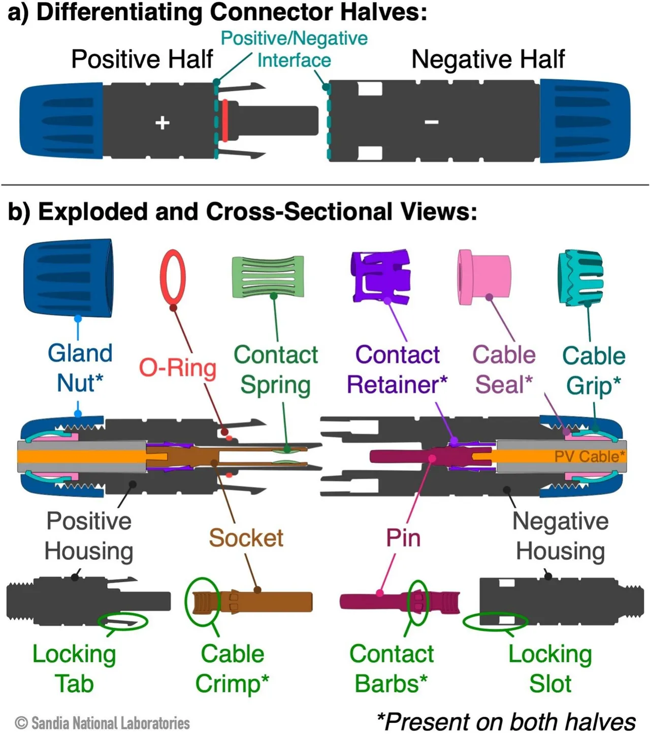
This diagram from Sandia National Laboratories breaks down the anatomy of a PV connector, highlighting the positive and negative interfaces, internal spring contacts, seals, crimps, and locking mechanisms.
✅ The gland nut (blue) and cable grip (turquoise) work together to clamp the cable and, with the cable seal, provide strain relief and sealing.
✅ The O-ring (red) is also part of the sealing system.
✅ The contact retainer (purple) holds the contact in place inside the housing. The locking tab/slot secures the positive and negative housings together. Together they prevent unwanted movement.
✅ The cable crimp ensures low-resistance connection between cable and contact, and the contact spring (green) maintains pressure and conductivity at the mating interface. Both reduce resistive heating under high current.
Connector failures remain a leading cause of PV underperformance, downtime, and fire incidents. Understanding the internal design helps engineers and technicians ensure proper assembly, minimize resistive heating, and extend system life.